Welcome,Flow Switches,Shanghai ZanKe Automation Technology Co., Ltd Hotline:18001874240
Language:
 ∷

∷
∷


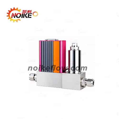
The NKFA-M Medium-Range Analog Mass Flow Meter/Controller is a thermal mass flow measurement and control instrument designed for medium-range gas flow applications. The series provides flow ranges from 30 SLM to 150 SLM, with a specified accuracy of ±1.0% FS, and supports analog signals including 0–5 VDC and 4–20 mA.
The NKFA-M series is available in two configurations: NKFA-MM Mass Flow Meter for flow measurement and NKFA-MC Mass Flow Controller for flow measurement and control. The product can be configured according to flow range, pressure rating, signal type, power supply, sealing material, and connection size.
Measurement principle: Thermal mass flow measurement.
Flow range: 30 SLM to 150 SLM.
Accuracy: ±1.0% FS.
Linearity: ±0.5% FS.
Repeatability: ±0.2% FS.
Response time: <2 s for the mass flow controller and <1.5 s for the mass flow meter.
Analog signals: 0–5 VDC and 4–20 mA.
Operating temperature: 0–50°C.
Base material: 316L.
Connection options: φ6, φ10, 1/4″, and 3/8″.
Available configurations: Mass Flow Meter and Mass Flow Controller.
The NKFA-M is a medium-range analog mass flow measurement and control series designed for gas flow applications requiring flow measurement, monitoring, or control.
The series includes:
NKFA-MM Mass Flow Meter
NKFA-MC Mass Flow Controller
The NKFA-M uses a thermal mass flow measurement principle. The product information describes a flow-splitting structure and thermal measurement method. This design provides fast response and is intended for flow measurement and control applications.
The main product features shown in the product specifications include:
Thermal measurement principle with fast response and high accuracy.
Flow-splitting pipeline structure.
Suitable for various low-pressure and high-pressure pipeline applications within the specified pressure range.
Short preheating time, low zero drift, and high reliability.
Supports analog input/output signals for connection with secondary instruments or flow computers for flow display and control.
The actual operating conditions should be confirmed according to the selected model and application requirements.
The NKFA-M uses a thermal mass flow measurement principle.
According to the product information, the measured gas is divided through the flow-splitting structure, with part of the gas flow passing through the sensor measurement section. The sensor detects the thermal changes associated with gas flow and converts the detected change into a flow signal.
The measurement process can be represented as:
Gas Flow → Thermal Change → Sensor Detection → Electrical Flow Signal
This principle is used for gas mass flow measurement within the specified flow range.
The NKFA-MM Mass Flow Meter is primarily used for gas flow measurement and signal output.
The measured flow can be converted into an analog signal such as:
0–5 VDC
4–20 mA
These signals can be used by external display instruments, control systems, PLCs, or flow calculation systems according to the selected configuration.
The NKFA-MC Mass Flow Controller combines flow measurement with flow control.
According to the product description, the mass flow controller consists of components including:
Mass flow sensor
Flow-splitting / differential-pressure component
Flow control valve
Amplification and control circuit
The basic control process can be described as:
Flow Measurement → Signal Processing → Comparison with Setpoint → Valve Adjustment → Flow Control
The control valve regulates the flow so that the actual flow approaches the set flow value.
According to the provided NKFA-M product specifications, the main technical parameters are as follows:
| Technical Parameter | NKFA-MC Mass Flow Controller | NKFA-MM Mass Flow Meter |
|---|---|---|
| Flow Range | 30–150 SLM | 30–150 SLM |
| Accuracy | ±1.0% FS | ±1.0% FS |
| Temperature | ±1°C | ±1°C |
| Linearity | ±0.5% FS | ±0.5% FS |
| Repeatability | ±0.2% FS | ±0.2% FS |
| Response Time | <2 s | <1.5 s |
| Analog Signal | 0–5 V, 4–20 mA | 0–5 V, 4–20 mA |
| Power Supply | ±15 VDC | 24 VDC |
| Operating Temperature | 0–50°C | 0–50°C |
| Working Pressure | 0.05–0.5 MPa | <30 kPa |
| Maximum Pressure | 3 MPa | 10 MPa |
| Electrical Connection | DB15 | DB15 |
| Leakage Rate | 1×10⁻⁵ SCCSHe | 1×10⁻⁵ SCCSHe |
| Temperature Coefficient | ±0.015% FS/°C | ±0.015% FS/°C |
| Base Material | 316L | 316L |
| Sealing Material | Fluororubber, PTFE, Chloroprene Rubber | Fluororubber, PTFE, Chloroprene Rubber |
| Connection Fittings | φ6, φ10, 1/4″, 3/8″ | φ6, φ10, 1/4″, 3/8″ |
Note: The specifications above are organized directly from the provided product information. The actual technical configuration should be confirmed according to the selected model and technical documentation.
The NKFA-M series is designed for medium-range gas flow measurement and control.
The listed flow range options include:
30 SLM
50 SLM
100 SLM
150 SLM
Therefore, the NKFA-M series covers a flow range of:
30 SLM–150 SLM
The appropriate range should be selected according to the actual operating flow requirements.
 NKFA-M Medium-Range Analog Mass Flow Meter/Controller
Selecting the appropriate NKFA-M configuration requires consideration of several key parameters.
The product selection includes:
[C] Mass Flow Controller
[M] Mass Flow Meter
Choose the NKFA-MC Mass Flow Controller when flow regulation is required.
Choose the NKFA-MM Mass Flow Meter when the primary requirement is flow measurement.
The product selection information provides:
[M] 3 MPa
[Z] 10 MPa — Mass Flow Meter only
Therefore, the pressure rating should be selected according to the actual system pressure and product type.
For the 10 MPa configuration, the product information specifies that it is available for the Mass Flow Meter only.
Available flow range options include:
[030L] 30 SLM
[050L] 50 SLM
[100L] 100 SLM
[150L] 150 SLM
The selected flow range should match the actual operating requirements of the gas flow system.
The available input signal options shown in the product selection information are:
[A1] 0–5 VDC
[A2] 4–20 mA
The appropriate input signal should be selected according to the interface requirements of the control system.
The available output signal options include:
[B1] 0–5 VDC
[B2] 4–20 mA
The signal type should be matched with the connected PLC, controller, display instrument, or other control equipment.
The product selection provides:
[S] ±15 VDC
[4] 24 VDC
The required power supply should be confirmed according to the selected configuration and system requirements.
Available sealing material options include:
[V] Fluororubber
[T] PTFE
[N] Chloroprene Rubber
[Y] Other
The sealing material should be selected according to the compatibility requirements of the measured medium.
The product selection information lists the following connection options:
[B] φ6
[C] φ10
[D] 1/4″
[G] 3/8″
[Y] Other — Contact the Manufacturer
The connection size should be selected according to the requirements of the gas pipeline system.
The working pressure differs between the NKFA-MC Mass Flow Controller and NKFA-MM Mass Flow Meter.
According to the provided specifications:
NKFA-MC Mass Flow Controller: 0.05–0.5 MPa
NKFA-MM Mass Flow Meter: <30 kPa
The actual pipeline pressure should therefore be confirmed before selecting the product.
The NKFA-M series covers 30–150 SLM.
Before installation, confirm the actual minimum, normal, and maximum operating flow to select the appropriate flow range.
Before connecting the instrument, verify:
Input signal
Output signal
Power supply
DB15 electrical connection
Incorrect electrical configuration may affect normal operation.
Confirm that the instrument connection matches the field pipeline before installation.
Available connection options include:
φ6, φ10, 1/4″, and 3/8″.
The sealing material should be selected according to the characteristics and compatibility requirements of the measured medium.
The listed options include:
Fluororubber, PTFE, and chloroprene rubber.
For medium-range gas flow measurement, selecting an appropriate flow range helps ensure that the instrument is properly matched to the actual operating conditions.
The NKFA-M provides 30, 50, 100, and 150 SLM flow range options.
The NKFA-MM Mass Flow Meter is primarily used for flow measurement and signal output.
The NKFA-MC Mass Flow Controller combines flow measurement with flow control and uses a control valve to regulate the flow according to the set value.
Yes. The product selection information includes 4–20 mA as an available analog input/output signal option.
It also provides 0–5 VDC.
The specified operating temperature is:
0–50°C.
The specified accuracy is:
±1.0% FS.
The product specifications also list:
Linearity: ±0.5% FS
Repeatability: ±0.2% FS
The NKFA-M series provides:
30 SLM, 50 SLM, 100 SLM, and 150 SLM
flow range options.
According to the provided product information, the NKFA-M series can be used in the following application fields:
Glass industry
Solar energy
Atmospheric monitoring
Industrial manufacturing
Petrochemical applications
Combustion and metallurgy
Gas generation and gas mixing
Environmental protection
Instrument analysis
The medium-range NKFA-M series is suitable for systems requiring gas flow measurement, monitoring, and control within the specified operating range.
Product Series: NKFA-M
Product Types:
NKFA-MM Mass Flow Meter
NKFA-MC Mass Flow Controller
Thermal mass flow measurement principle
Medium-range gas flow measurement
30–150 SLM flow range
±1.0% FS accuracy
±0.5% FS linearity
±0.2% FS repeatability
Fast response
0–5 VDC / 4–20 mA analog signals
316L base material
Multiple sealing material options
Multiple connection specifications
The NKFA-M is a medium-range analog mass flow meter/controller series based on a thermal mass flow measurement principle.
The NKFA-M covers flow ranges from 30 SLM to 150 SLM, with available options of 30, 50, 100, and 150 SLM.
The specified accuracy is ±1.0% FS.
The NKFA-MM is a mass flow meter designed for flow measurement, while the NKFA-MC is a mass flow controller designed for both flow measurement and control.
Yes. The NKFA-M product selection includes 4–20 mA and 0–5 VDC analog signal options.
The specified operating temperature is 0–50°C.
The listed connection options are φ6, φ10, 1/4″, and 3/8″, with other options available by contacting the manufacturer.
The listed sealing options include fluororubber, PTFE, and chloroprene rubber, with other options available according to the product selection.
The NKFA-M Medium-Range Analog Mass Flow Meter/Controller is a thermal mass flow instrument designed for gas flow measurement and control applications in the 30–150 SLM range.
The series provides a specified accuracy of ±1.0% FS, linearity of ±0.5% FS, and repeatability of ±0.2% FS. It supports 0–5 VDC and 4–20 mA analog signal configurations and provides multiple options for power supply, sealing material, and pipeline connections.
The NKFA-M series includes both the NKFA-MM Mass Flow Meter and NKFA-MC Mass Flow Controller, allowing users to select the appropriate configuration according to whether the application requires flow measurement or flow measurement combined with flow control.
For proper product selection, the key parameters to confirm include product type, flow range, working pressure, input/output signal, power supply, sealing material, and connection size.
If you are looking for a medium-range gas mass flow meter or mass flow controller, please provide the following application information:
Measured gas
Minimum flow rate
Normal flow rate
Maximum flow rate
Working pressure
Operating temperature
Required accuracy
Input/output signal
Power supply
Connection size
Sealing material requirements
Based on these parameters, the appropriate NKFA-M Mass Flow Meter or Mass Flow Controller configuration can be determined.
Contact:Mr.Tu
Tel:18001874240
Email:noike009@foxmail.com