Welcome,Flow Switches,Shanghai ZanKe Automation Technology Co., Ltd Hotline:18001874240
Language: Chinese∷  English

Home> English Website products flowmeters

  • Pulse Output Positive Displacement Dual Oval Gear Flowmeter
Pulse Output Positive Displacement Dual Oval Gear Flowmeter

Pulse Output Positive Displacement Dual Oval Gear Flowmeter

  • Brand:ZANKE
  • Model:
  • Description:Pulse Output Positive Displacement Dual Oval Gear FlowmeterBrand: Shanghai
  • Online Consultation

Pulse Output Positive Displacement Dual Oval Gear Flowmeter

Brand: Shanghai Zanke Automation Co., Ltd.
Model:

Product Description

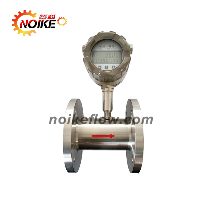
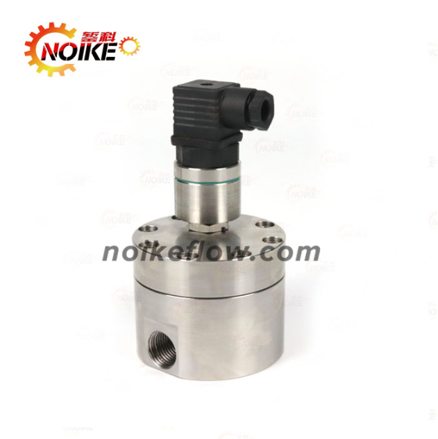
The NKGF gear flow sensor features built-in dual-gear operation, which calculates the volume of medium passing through via high-precision gear volume measurement, enabling the measurement of micro-fluid media. It is a new type of positive displacement flow sensor, used for precise continuous or intermittent measurement of liquid flow or instantaneous flow in pipelines.

Main Application Range of NKGF Series Oval Gear Flowmeters

The NKGF gear flow sensor is widely used for low-flow accurate measurement in various industries. Suitable media include: additives, fuels, flotation tanks in water treatment, corrosion inhibitors, catalysts, emulsifiers, oils, greases, fragrances, adhesives, solvents, inks, pesticides and some high-viscosity media. Application industries cover automotive, aerospace, mining, electric power, chemical industry, pharmaceuticals, food, coatings, petroleum, environmental protection, printing and other sectors.


It is particularly suitable for flow measurement of high-viscosity media such as heavy oil, polyvinyl alcohol, resins (capable of measuring fluids with viscosity up to 10,000 cSt). It has small volume, light weight, low vibration and noise during operation, and stable operation. It can also be used for measuring micro-flows in small-diameter pipes, with low starting flow and wide range ratio, making it suitable for metering liquid flows with large fluctuations. The metering accuracy is not affected by changes in pressure and flow, with stable performance, long service life and large flow capacity.


  • Measurement of resins and glues

  • Measurement of hydraulic oil, lubricating oil and greases; measurement of fuel oil; measurement of inks and asphalt

  • Measurement of liquid nitrogen, refrigerants and solvents; measurement of edible oil, fish oil and food filling

  • Measurement of fluids with chemical and anti-corrosion requirements; fluid quantitative control systems

Technical Parameters of Oval Gear Flowmeters

  • Measurement range: 0.005~330L/min (custom ranges available)

  • Output signal: Pulse, 4-20mA, PNP/NPN

  • Measurement accuracy: 0.5% F.S

  • Repeatability: 0.1% F.S

  • Power supply: 16~30VDC

  • Pressure resistance: Aluminum (150bar); Stainless steel (400bar); PP (50bar)

  • Material: Shell: Aluminum, stainless steel, PP; Display: Stainless steel

Dimension Diagram of Gear Flowmeters

ModelABDHEFGMeasurement Range
GF280558316402*M6G1/45-300mL/min
GF480558316552*M6G3/80.1-3L/min
GF680628314552*M6G1/20.15-8L/min
GF1080658314552*M6G1/20.8-20L/min
GF151106511328902*M6G3/43-50L/min
GF2514085158401102*M8G120-200L/min
GF32160100218451802*M8M35*1.530-330L/min

Installation Requirements for Oval Gear Flowmeters

  1. The on-site installation position of the transmitter should avoid environments with high temperature, strong mechanical vibration, strong magnetic field interference and strong corrosiveness as much as possible, and choose a location that is easy for maintenance and repair.

  2. The transmitter should generally be installed horizontally, and the sensor must be firmly installed on the assembly with screws. If vertical installation is necessary, the liquid direction must be upward. The liquid should fill the pipeline without bubbles.

  3. When installing the sensor on a new pipeline, it is recommended to install a filter upstream of the transmitter to prevent impurities in the pipeline from entering the transmitter.

  4. When installing the transmitter and its accessories, their center lines should be aligned with the pipeline center line, and the sealing gasket at the connection should not protrude into the liquid.

  5. If a flow control valve needs to be installed, it must be installed on the downstream side of the sensor.

  6. To avoid affecting the normal transmission of liquid during maintenance, a bypass pipeline should be installed at the installation position of the transmitter.

  7. Magnetic fields and similar interference sources near the gear flow transmitter may affect the sensor's signal acquisition. The connection between the transmitter and the display instrument should use a metal-shielded cable, and the shielding layer of the transmission cable should be grounded at one point on the display instrument side.